Choke points in crusher cavities are critical zones where material flow is restricted, directly impacting crushing efficiency, product gradation, and equipment longevity. These occur when the feed material cannot pass freely through the crushing chamber due to improper cavity design, excessive feed size, or poor operational practices. Addressing choke points requires a combination of optimized cavity geometry, proper feed control, and real-time monitoring.
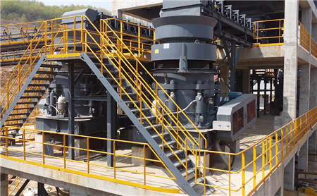
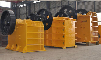
Modern crushers (e.g., cone crushers, jaw crushers) employ advanced cavity profiles to minimize choke points. Key design factors include:
– Crushing Chamber Geometry: Steeper angles reduce recirculation but may increase wear.
– Eccentric Throw: Adjustable throws (e.g., 16–48 mm) optimize particle size reduction.
– Closed-Side Setting (CSS): Critical for controlling discharge gradation (e.g., 10–50 mm for secondary crushing).
| Parameter | Cone Crusher (Example: CH860) | Jaw Crusher (Example: CJ615) |
|---|---|---|
| Max Feed Size | 275 mm | 1,070 mm |
| CSS Range | 8–48 mm | 75–200 mm |
| Power | 500 kW | 200 kW |
| Cavity Type Options | Coarse/Medium/Fine | Standard/Deep/Shallow |
1. Feed Control: Use pre-screening (<5% oversize) to match crusher capacity.
2. Cavity Selection: Match liner profiles to material hardness (e.g., MX liners for abrasive granite).
3. Automation: Utilize ASRi™ or similar systems to dynamically adjust CSS based on load.
Symptom: Frequent power spikes + uneven wear patterns.