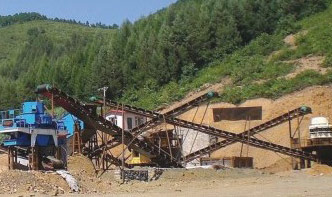
A typical aggregate processing plant involves multiple stages to transform raw materials into high-quality sand and gravel. The core equipment includes crushers, screens, conveyors, and washing systems. Below is a simplified flow diagram:
1. Primary Crushing: Raw materials (e.g., granite, limestone) are fed into a jaw crusher (e.g., 600×900 mm feed opening) for coarse reduction.
2. Secondary Crushing: Cone crushers (e.g., 200 tph capacity) further break down the material to 20–50 mm.
3. Screening: Vibrating screens (e.g., 3-deck, 1800×4800 mm) separate aggregates into different sizes (0–5mm, 5–20mm, 20–40mm).
4. Tertiary Crushing/Sand Making: VSI crushers (e.g., 100–300 tph) produce fine sand (0–5mm) with high cubicity.
5. Washing & Dewatering: Sand washers and hydrocyclones remove impurities and control moisture (<10%).
| Equipment | Model | Capacity | Power |
|---|---|---|---|
| Jaw Crusher | PE-600×900 | 50–160 tph | 75 kW |
| Cone Crusher | HPT-200 | 120–250 tph | 160 kW |
| VSI Crusher | B-9100SE | 100–300 tph | 250 kW |
| Screening Machine | 3YK-2160 | 80–500 tph | 30 kW |
Q: How to reduce dust in the crushing plant?
A: Install dust suppression systems (e.g., water sprays) and enclosed conveyors.
Q: What’s the ideal moisture