A gold processing plant typically includes crushing, grinding, leaching, and refining stages. The core equipment involves jaw crushers, cone crushers, ball mills, and carbon-in-pulp (CIP) systems. Below is a streamlined process flow:
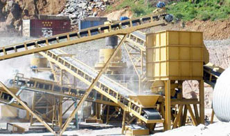
1. Primary Crushing: Gold ore is fed into a jaw crusher (e.g., feed size: ≤1,000mm; output: 150–300mm).
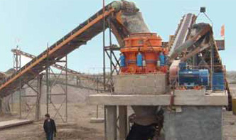
2. Secondary Crushing: Cone crushers further reduce ore to ≤50mm.
3. Grinding: Ball mills pulverize ore to ≤0.074mm for leaching.
4. Leaching & Adsorption: Cyanide solution extracts gold, which is adsorbed onto activated carbon.
5. Refining: Electrowinning or smelting produces pure gold bars.
| Equipment | Model | Key Parameters |
|---|---|---|
| Jaw Crusher | PE-600×900 | Capacity: 50–160t/h; Power: 75kW |
| Cone Crusher | HPT300 | Capacity: 120–400t/h; Power: 315kW |
| Ball Mill | MQY2740 | Capacity: 15–30t/h; Power: 400kW |
| CIP System | CIP-1000 | Tank Volume: 1,000m³; Recovery Rate: ≥95% |
Q1: How to optimize gold recovery rates?
A1: Ensure particle size ≤0.074mm post-grinding and maintain cyanide concentration at 0.03–0.08%.
Q2: Common issues in CIP systems?
A2: Carbon blockage or low adsorption efficiency—check screen apertures and carbon activity monthly.
Project: Tanzania 1,200t/d Gold Plant
Challenge: High clay content hindered